Tour Series FAQs
- Accessory Compatibility
- Installation
- Calibration
- Standard Maintenance
- Troubleshooting
- Storage
What are the dimensions of the Tour and Tour Pro foot pedal?
Tour Pro: 5.05” height x 9.16” width x 14.43” length
Tour: 5.05” height x 8.5” width x 14.43” length
What recessed trays are compatible with my Tour Pro?
We currently know the following are compatible with the Tour and Tour Pro foot pedals. Please refer to the pedal dimensions to confirm additional aftermarket accessories.
- Rod Saver Flat Foot Pedal Tray
- TB Nation Trolling Motor Foot Pedal Tray
- Panther Marine Tech Foot Pedal Tray
Can I use a QRB with my Tour or Tour Pro?
Yes, our Universal Quick Release Bracket works with our Tour Series motors. This QRB also works with most competitor hole patterns as well.
Which sonar units is my HD+ enabled motor compatible with?
- Lowrance 9-Pin (8M4004174): HDS Carbon, HDS Live, Elite Ti/Ti2, Elite FS
- Lowrance 7-Pin (8M4004175): HDS, HDS Gen 2, HDS Gen 2T, HDS Gen 3, HDS Carbon, Hook/Hook2
- Humminbird 11-Pin (8M4004176): Solix/Onix
- Humminbird 7-Pin (8M4004177): Helix, 500, 600, 700, 800, 900, 1100
- Garmin 8-Pin (8M4004178): GPSMap, EchoMap
- Raymarine Element (8M4004179): Element Series
- Raymarine Axiom (8M4004180): Axiom Series
- New Garmin EchoMap Units with a yellow transducer port with require an additional cable. Garmin Part#101-12122-10, sold separately.
- Hook2 Sonars will require an additional cable adapter cable. Lowrance Part #000-14068-001, sold separately.
- Only Lowrance/Simrad MFDs will NMEA Network
What props work on my Tour or Tour Pro?
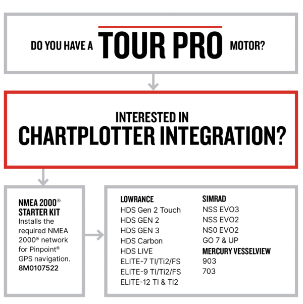
How Can I connect my motor to a chartplotter for advanced navigation features?
How do I install my new Tour or Tour Pro?
How do I install my gas shocks on my Tour or Tour Pro?
How do I connect my Tour Pro motor to my chartplotter?
Tour Pro can be NMEA 2000 Networked for additional features on your Lowrance/Simrad MFDs.
Please use this NMEA 2000 Network chart to properly route your NMEA 2000 Network.
If NMEA networking, ensure your network is powered off a single switched 12v source. If multiple power nodes are needed to balance the network, they should be added to the same 12v switched source.
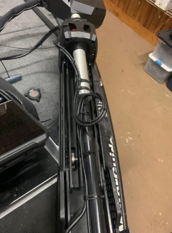
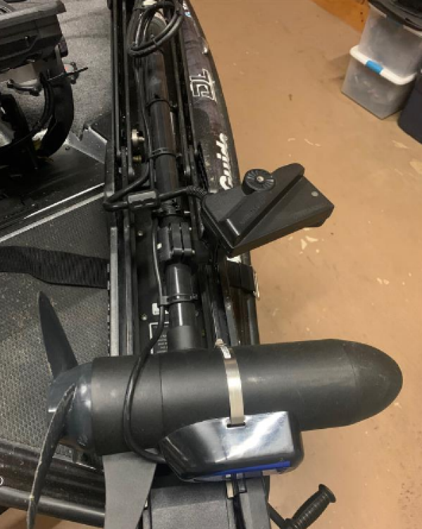
What is the proper orientation and cable layout for Tour Pro (GPS true cable steer motor)?
The trolling motor head of the Tour Pro should be perpendicular to the mount, and cable layout should be in a "lazy C" shape, avoiding sharp bends. Do not install cable ties to the steering cables. Accessories should be ran along side the mount, free from pinch points. Installing the Tour Pro with sharp bends in the cable, incorrect head orientation, and/or zip ties added to the steering system can introduce poor power steeting and Pinpoint autopilot performance, while increasing the overall effort needed to steer the motor with the foot pedal.
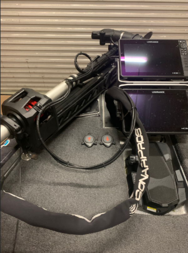
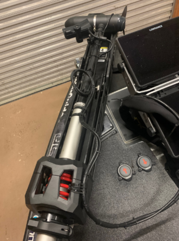
HOW SHOULD I PROPERLY RUN EXTERNAL CABLES ON MY TOUR PRO?
Avoid installing Zip Ties on the cable system of the Tour Pro. This can induce excessive cable tension, causing poor performance of the Pinpoint GPS and Cable Steering System. If zip ties are used, install them loose. You may also use a Troll Jacket or similar accessory to properly contain your cables without straining your motor. A great example of proper routing and use of cable ties on a MotorGuide Tour Pro + Lowrance HDS and ActiveTarget system is shown below.
We have also created a video showing proper routing available here.
When do I need to calibrate my motor?
If traveling more than 250 miles from your last calibration point or the Tour Pro isn’t holding as accurate as expected, it is recommended you recalibrate the Tour Pro to ensure the best possible GPS accuracy.
How do I sync my remote?
How do I calibrate my motor?
Watch this quick video and follow the instructions below to calibrate your motor.
Use your remote to complete Compass Calibration – M111
1. A. If performing the compass calibration with the boat in the water: locate a suitable area clear of obstructions to navigation (both above and below the waterline) to perform the compass calibration
B. If performing the compass calibration with the boat on the trailer: locate a suitable area clear of obstructions to perform the compass calibration.
2. Deploy the trolling motor. Adjust the motor height so that the bottom of the head is 6 in. (15.2 cm) above the depth collar and the motor. If performing the compass calibration with the boat in the water, verify that you are in a location where your trolling motor and primary propulsion engine will not hit bottom or other obstructions.
3. Press and hold the manual mode button, then press 1, 1, 1. The trolling motor will emit three ascending-tone beeps and the GPS status indicator light will turn off.
4. A. If performing the compass calibration with the boat in the water: use the primary propulsion engine to slowly drive the boat in two complete circles.
B. If performing the compass calibration with the boat on the trailer: tow the boat in two complete circles.
5. Two beeps will occur when very close to completing the second circle. The GPS status indicator light will turn on and a beep will occur, signaling a successful compass calibration.
6. For initial installations, repeat steps 1-5 two additional times to ensure the motor is fully calibrated to your specific boat and geographic region.
NOTES:
- A fixed GPS position (illuminated GPS indicator light) and a paired Tour Pro remote is required to complete Compass Calibration.
- The more you calibrate, the better the accuracy. We recommend 2-3 full calibrations for best results.
- Compass calibration should NOT be completed using Tour Pro for propulsion as this could negatively impact Pinpoint GPS performance.
What do I need to do if moving my motor to a new boat?
If your trolling motor has been moved from one boat to another, it is recommended you recalibrate your Tour Pro to ensure correct heading lock performance, also known as Mounting Angle Keel Calibration.
A paired Tour Pro remote is required to complete Keel Calibration
1. Power up and deploy the trolling motor. Adjust the motor height so that the bottom of the head is 6” above the depth collar and the motor is clear of any obstructions while turning.
2. Using the Left Turn and Right Turn Buttons, steer the unit so that it is facing straight ahead, parallel to the keel of the boat, with the nose cone of the motor facing forward.
3. Once the lower unit is positioned as close to parallel as possible with the keel. Press and hold the Manual Mode (M) button.
4. While holding M, Press and release the 1, 1, 2, button sequence. The Tour Pro will emit an audible tone and flash the indicator light when complete.
When moving from boat to boat, be sure not to twist the steering cables while transporting. If the steering is inconsistent, or the “jog” function seems to be angled, recalibrate using M284 followed by M285 – Sensor Calibration.
Where do I find my serial number?
What should I have on board at all times?
Be sure to always have your Tour Pro wireless remote, the GPS Quick Start Guide, and 2 NEW AAA Batteries.
When should I lubricate my motor?
You should lubricate your motor every 100 hours of use and/or annually.
- Wipe free contaminated lubrication and dirt
- Lube the latch hooks and strikers using MotorGuide Tour Latch Grease (Part no: 8M4005246)
- Pivot Pins can also be lubricated with WD-40.
What do I do if my GPS/Anchor isn’t working?
1. Check for satellite signal within 5 mins of power up in deployed position
a. If no signal, power cycle while the motor is deployed
2. Check for environmental factors (anchors near, speakers, iron ore lake sediments, infrastructure critical to national security)
3. Check not under bridge/overhanging structure
4. Check that GPS compass calibration is complete M111
5. Check that keel alignment calibration is complete M112
6. Perform Foot Pedal End-of-travel Calibration M284
a. Deploy the Motor (Thrust Command must be OFF, Tour Pro System ON), verify 360* steering/rotation can be achieved by the lower unit without obsruction.
b. Rotate the foot pedal to the neutral position
c. Using the paired Remote, hold the M button, and press 2, 8, 4, the foot pedal will drive automatically from heel down to toe down position and beep. When complete the unit will remain at heel down position for more than 10 secs.
d. IMPORTANT: A power cycle should be done after completion of M284 or M285.
7. Perform Sensor Module Calibration M285
a. Deploy the Motor (Thrust Command must be OFF, Tour Pro System ON), verify 360* steering/rotation can be achieved by the lower unit without obsruction.
b. Place the foot pedal in 3/4 ‘s Heel Down Position
c. Using a paired Remote, hold the M button, and press 2, 8, 5, the foot pedal will drive automatically. When complete the foot pedal will remain in the Toe Down position for more than 10 secs
d. IMPORTANT: A power cycle should be done after completion of M284 or M285.
8. Adjust Steering Cable Tension (too loose or too tight will cause poor pinpoint functions)
a. Remove the foot pedal from the deck.
b. Adjust the cable tension by turning the screw clockwise to increase tension, and counterclockwise to decrease tension. Adjust the cable tension until there is minimal play (0.125") in the foot pedal pad.
c. NOTE: Tension adjustment is sensitive, adjustments should be made at no more than ¼” at a time. Rock the pedal from Toe Down to Heel Down after adjusting
d. Ensure the foot pedal cables are not kinked or twisted
e. Use the paired Pinpoint remote to verify the cables have not been over-tensioned
f. Place the foot pedal in the toe down position
g. Hold the left arrow on the remote to rotate the unit counterclockwise until the foot pedal is heel down
h. Hold the right arrow on the remote to rotate the unit clockwise until the foot pedal is toe down. The head should rotate 360* without shuttering. If shuttering occurs, decrease cable tension.
i. Repeat M284/M285 Calibrations after any Tension Adjustments are made.
Video: Troubleshooting GPS/Anchor with Barry Stokes
If these steps do not resolve your issue, please contact your local service center or Customer Service.
What do I do if I’m getting sonar interference?
1. Lower the sonar sensitivity, also known as gain. Refer to the documents included with your sonar display.
a. Change the sensitivity to an automatic setting.
2. If the automatic setting does not reduce sonar interference, manually change the sensitivity to 55–65% of the maximum setting.
3. Verify that the transducers cables or any networking cables connected to the MFD are not routed near trolling motor power cables or batteries.
4. Ensure that the positive (+) and negative (–) power cables are installed next to each other. This helps cancel any EMI.
5. Inspect the transducer cable for damage, nicks, or cuts. Replace the transducer cable if it is damaged.
a. Connect the sonar display to a separate accessory battery with only the sonar display connected. This will verify if the interference is coming from the power cables or the transducer cable
b. If the interference stops when the sonar display is connected to a separate accessory battery, inspect the boat wiring. Most likely, there’s a problem with the ground (–) connection.
c. If the interference continues, it is likely coming from the transducer or transducer cable
d. If using an Ethernet networked system, toggle to a different transducer in the network (furthest away from the Trolling Motor)
6. Install a Ferrite Bead (RF Choke) onto the power cables of the displays showing interference.
7. Remove the propeller from the Tour Pro, retest to see if interference is being caused by propeller harmonics
If these steps do not resolve your issue, please contact your local service center or Customer Service.
What do I do if I’m hearing excessive squeaking?
Ensure the 360 breakaway bolts are fully engaged and the stow/deploy system has been properly lubricated.
How do I replace the Stow Cable on my Tour Series Motor?
How do I adjust my foot pedal tension?
How do I properly store my motor at the end of a day?
Always unplug your Tour Pro from the 36/24v DC port, or trip your trolling motor power breaker, at the end of the day before charging.
- The Tour Pro’s circuitry and onboard components need an opportunity to reset to perform optimally.
Also check the propeller and propeller shaft, remove any debris.
How do I prepare my motor for long term storage?
Store the Tour Pro in a dry location where it will not be affected by temperatures below -20*F.
If the motor is stored in temperatures below 32*F, it should be operated slowly for the first 15 mins before going above 30% throttle.
If after 15 mins of operation, the trolling motor seems to be underperforming above 50% throttle or shutting off completely. Check the following:
- Individual Deep Cycle Battery Voltage
- Trolling Motor Circuit Breaker continuity
- Inspect Batteries for loose connections
- Load Test individual batteries (100A 12v Load Tester)
- Verify 24/36v at and through the trolling motor DC port